Overview
This is a memo on how to create polylines using the polygon tool in Annotorious v2.
Background
The Annotorious v2 website is available at the following link.
As shown below, polygons can be drawn.

However, a tool for drawing polylines in a similar manner did not appear to be provided, including the following plugin.
 GitHub
Customization
When a polygon like the following is created:
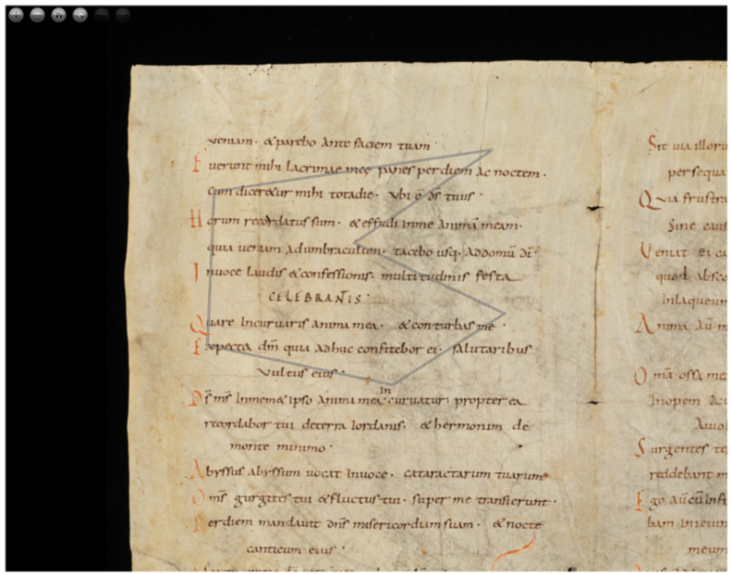
The following JSON file is generated:
{
    "type": "Annotation",
    "body": [
        {
            "type": "TextualBody",
            "value": "polygon",
            "purpose": "commenting"
        }
    ],
    "target": {
        "source": "https://www.e-codices.unifr.ch/loris/gau/gau-Fragment/gau-Fragment_frag001a.jp2/full/full/0/default/jpg",
        "selector": {
            "type": "SvgSelector",
            "value": "<svg><polygon points=\"3383.121337890625,1290.137451171875 945.135498046875,1658.426513671875 885.9696655273438,3003.352294921875 2508.54150390625,3348.424072265625 3485.021484375,2724.35791015625 2170.811767578125,2107.6337890625\" /></svg>"
        }
    },
    "@context": "http://www.w3.org/ns/anno.jsonld",
    "id": "#c469b1a3-8902-4443-8f54-47df8bb87d7e"
}
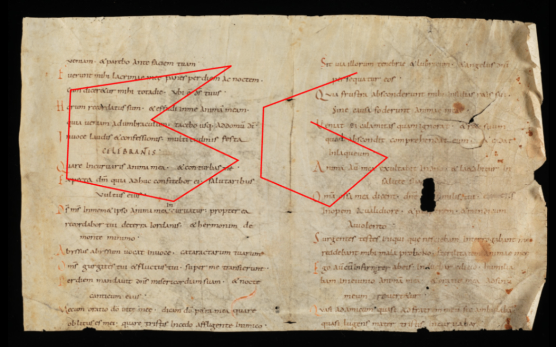
For the above, I prepared a variable like autoClose, and when it is false, added processing to replace the string "polygon" with "polyline."
anno.on("createAnnotation", function (selection: any) {
      if(!autoClose.value) {
        selection.target.selector.value = selection.target.selector.value.replace("polygon", "polyline");
      }
      ...
    });
This allows you to switch between polygon and polyline based on the polygon tool, as shown below.
Representation in TEI/XML
As an example of polygon representation in TEI/XML, you can use the path element. In this case, for polygons, the starting point is added after the ending point to represent a closed shape.
<facsimile>
  <surface ulx="0" uly="0" lrx="8176" lry="6132">
    <graphic url="https://www.e-codices.unifr.ch/loris/gau/gau-Fragment/gau-Fragment_frag001a.jp2/full/full/0/default/jpg" />
    <zone xml:id="layer_000" change="#ch_layer_000" n="layer_01" type="layer">
      <zone xml:id="sign_layer_000_0000" change="#ch_sign_layer_000_0000" type="sign">
        <!-- polygon -->
        <path points="1290.137451171875,3383.121337890625 1658.426513671875,945.135498046875 3003.352294921875,885.9696655273438 3348.424072265625,2508.54150390625 2724.35791015625,3485.021484375 2107.6337890625,2170.811767578125 1290.137451171875,3383.121337890625"></path>
      </zone>
      <zone xml:id="sign_layer_000_0001" change="#ch_sign_layer_000_0001" type="sign">
        <!-- polyline -->
        <path points="1393.265625,5290.81005859375 1921.02783203125,3869.745849609375 2982.731689453125,3829.64013671875 3428.122802734375,4874.005859375 2683.244384765625,5741.7509765625 2138.024169921875,4582.19775390625"></path>
      </zone>
    </zone>
  </surface>
</facsimile>
Depending on the application, closed shapes may be drawn even when the start and end points do not match, but we hope this serves as a useful reference for distinguishing between polygon and polyline.
Summary
We hope this serves as a useful reference for expressing polylines using Annotorious v2.
Note that the latest version of Annotorious is v3, and a similar approach should be applicable there as well.



Comments
…